Introduction
Choosing a bearing is not just a catalog exercise; it is a design decision that affects load capacity, speed, stiffness, friction, service life, and maintenance risk across the entire machine. The right choice depends on how radial and axial loads interact with operating speed, lubrication, temperature, contamination, and mounting conditions, including the fit between the bearing, shaft, and housing. This article outlines the main criteria used to compare bearing types and explains how fit selection influences performance, internal clearance, and failure risk. By the end, readers will have a practical framework for matching bearing characteristics to real operating conditions and avoiding common specification errors.
Why Bearing Selection Matters
Specifying the correct bearing is a foundational engineering discipline that directly dictates the mechanical integrity, efficiency, and longevity of rotating equipment. While bearings may superficially appear as highly commoditized components, the engineering physics governing their operation are deeply complex, involving non-linear contact mechanics, elastohydrodynamic lubrication, and precise material science. Selecting the optimal bearing requires a rigorous analysis of application-specific boundary conditions rather than relying on historical precedent or catalog approximations.
When engineers treat bearing specification as an afterthought, the resulting mechanical systems are frequently plagued by sub-optimal performance metrics, excessive vibration, and catastrophic premature failures. A systematic approach to bearing selection mitigates these risks, ensuring that the chosen component harmonizes with the shaft, housing, and external environmental variables.
Lifecycle impact on reliability and cost
The financial and operational implications of bearing selection extend far beyond the initial procurement cost. In industrial applications, the total cost of ownership (TCO) is heavily skewed toward maintenance intervals and unplanned downtime. For instance, a bearing costing $500 can easily induce $50,000 in lost production revenue if it fails prematurely on a critical path asset. Engineers typically design for a specific L10 basic rating life—often targeting 100,000 hours for continuous-duty industrial gearboxes or power generation equipment.
Achieving this target lifecycle requires precise alignment between the bearing’s dynamic load capacity and the actual application loads. Over-engineering by selecting a bearing with an excessively high load rating can be just as detrimental as under-sizing; over-sized bearings operating under minimum load conditions (typically requiring at least 2% of the dynamic load rating) are susceptible to roller skidding and adhesive wear, drastically reducing reliability.
Operating risks of poor specification
Failure to accurately define operating parameters during the specification phase introduces severe operational risks. Industry data indicates that while approximately 34% of premature bearing failures stem from lubrication issues, a significant 16% are directly attributable to poor initial selection and improper fits. When a bearing is subjected to loads, speeds, or temperatures outside its design envelope, the resulting distress manifests rapidly.
Common failure modes resulting from specification errors include true brinelling from static overloads, micro-spalling due to inadequate elastohydrodynamic film thickness, and cage fracturing from excessive centrifugal forces at high speeds. These failure modes not only destroy the bearing but frequently cause collateral damage to shafts, housings, and adjacent gearing, necessitating extensive and costly mechanical overhauls.
Technical Criteria for Bearing Selection
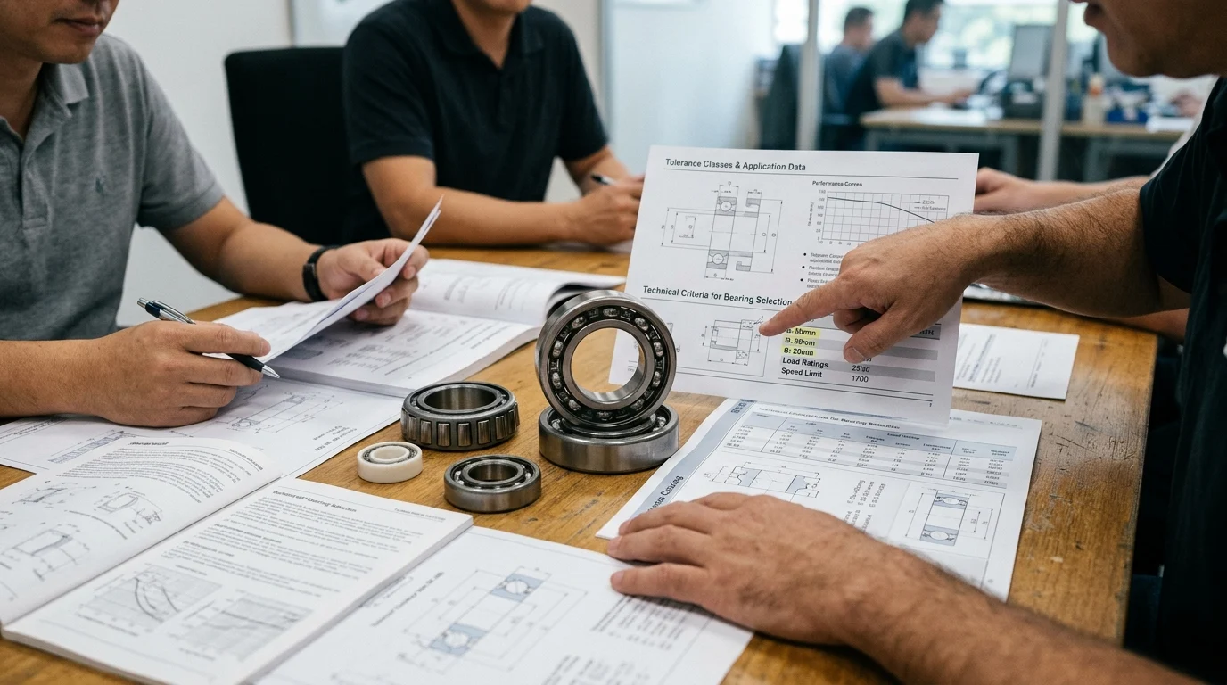
Translating mechanical requirements into a specific bearing geometry requires evaluating a matrix of interacting technical criteria. No single parameter can be isolated; speed capabilities influence lubrication choices, while load magnitudes dictate the internal clearance required to prevent catastrophic preloading during operation.
Load, speed, stiffness, and misalignment
The fundamental drivers of bearing architecture are the applied loads (radial, axial, or combined) and the rotational speed. Dynamic load rating (C) and static load rating (C0) must be evaluated against the equivalent dynamic bearing load (P). For high-speed applications, engineers utilize the speed factor (ndm), calculated as the pitch diameter in millimeters multiplied by the speed in RPM. Machine tool spindles frequently demand ndm values exceeding 1,000,000, necessitating precision angular contact ball bearings with ceramic rolling elements.
Stiffness requirements dictate the internal geometry and contact angles, particularly in precision tooling where shaft deflection must be minimized. Additionally, structural misalignment must be quantified. While deep groove ball bearings can typically accommodate less than 0.15 degrees of misalignment, applications with significant shaft bending may require spherical roller bearingss](https://www.demy-bearings.com) capable of compensating for up to 2.0 degrees of dynamic misalignment.
Fits, internal clearance, and tolerances
Dimensional tolerances and fits govern how the bearing interacts with its mating components. Bearings are manufactured to specific ISO tolerance classes (e.g., Normal, P6, P5, P4), with higher precision classes required for applications demanding tight runout control. The selection of shaft and housing fits—whether interference (press) or clearance (slip)—depends on the nature of the load (rotating vs. stationary ring).
Crucially, an interference fit expands the inner ring and compresses the outer ring, reducing the bearing’s radial internal clearance (RIC). If a heavy interference fit is mandated, engineers must specify a bearing with a larger initial internal clearance, such as a C3 or C4 designation. For example, a standard interference fit might reduce internal clearance by 0.015 mm to 0.030 mm; failing to account for this can result in a negative operating clearance, leading to rapid thermal runaway and seizure.
Lubrication, sealing, temperature, and contamination
The operational environment dictates the tribological and material requirements. Standard bearing steel (such as 52100 or 100Cr6) undergoes dimensional instability at elevated temperatures and is typically limited to operating temperatures below 120°C. If continuous operation exceeds 150°C, the bearing rings must undergo special tempering processes (e.g., S1 or S2 stabilization) to prevent metallurgical transformation and volume expansion.
Lubrication selection—grease versus oil—is driven by the operating speed and thermal dissipation requirements. Grease is preferred for its sealing properties and lower maintenance overhead but is generally limited to lower ndm values. In highly contaminated environments, such as mining or agricultural machinery, robust sealing solutions (like triple-lip elastomer seals or labyrinth seals) are mandatory to prevent particulate ingress, which rapidly degrades the lubricant and initiates three-body abrasive wear.
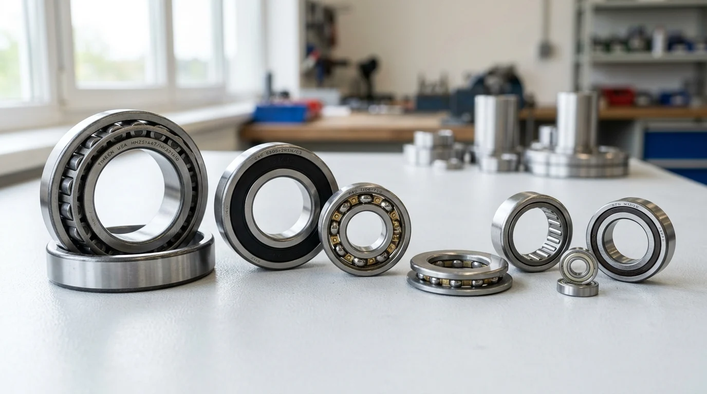
Comparing Bearing Types
The morphological differences between rolling elements—specifically whether they utilize point contact or line contact—fundamentally alter the bearing’s performance characteristics. Navigating the diverse catalog of bearing types requires an understanding of how internal geometry responds to macroscopic application forces.
Key differences between major bearing types
The primary distinction among bearing types lies in their load-carrying distribution and kinematic behavior. Deep groove ball bearings are highly versatile, offering exceptional speed capabilities and low friction, but are limited in heavy load applications. Conversely, cylindrical roller bearings excel in supporting massive radial loads due to their extended contact area but offer zero axial load capacity unless specifically flanged.
| Bearing Type | Contact Morphology | Relative Radial Capacity | Relative Speed Limit | Max Misalignment Tolerance |
|---|---|---|---|---|
| Deep Groove Ball | Point | Low to Medium | Very High | < 0.15° |
| Angular Contact Ball | Point (Angled) | Medium | High | < 0.05° |
| Cylindrical Roller | Line | High | Medium to High | < 0.05° |
| Spherical Roller | Line (Barrel) | Very High | Low to Medium | 1.5° to 2.0° |
| Tapered Roller | Line (Conical) | High (Combined) | Medium | < 0.05° |
Understanding these inherent limitations allows engineers to combine bearing types strategically. A common arrangement utilizes a fixed bearing (e.g., a double-row angular contact bearing) to locate the shaft axially, paired with a floating bearing (e.g., a cylindrical roller bearing) to accommodate thermal expansion of the shaft without inducing parasitic thrust loads.
When to use ball vs roller bearings
The decision between ball and roller bearings hinges primarily on the magnitude of the applied load and the resulting Hertzian contact stress. Because ball bearings utilize point contact, the stress concentration at the raceway is significantly higher under equivalent loads compared to the line contact of a roller bearing. As a general heuristic, a roller bearing provides roughly 3 to 5 times the radial load capacity of a comparably sized ball bearing.
However, this increased load capacity comes at a kinematic cost. The line contact in roller bearings generates higher friction and is more susceptible to edge loading if misalignment occurs. Consequently, roller bearings typically suffer a 20% to 30% reduction in maximum permissible speed compared to ball bearings of the same bore diameter. Therefore, ball bearings are the default choice for high-speed electric motors and precision spindles, while roller bearings dominate heavy-duty gearboxes, rolling mills, and wind turbine main shafts.
Bearing Selection Process
Transitioning from theoretical requirements to a finalized bill of materials demands a highly structured, iterative workflow. The bearing selection process is rarely linear; uncovering a thermal constraint in step four frequently necessitates returning to step two to select a different bearing architecture or lubrication strategy.
Step-by-step selection workflow
The standard selection workflow begins with comprehensively documenting the application’s boundary conditions: minimum and maximum loads, speed profiles, duty cycles, and ambient temperatures. Based on these inputs, engineers select the general bearing type (e.g., tapered roller vs. deep groove ball) that aligns with the load direction and magnitude.
Once the type is selected, the specific size is determined by calculating the required dynamic load rating to meet the target L10 life. Following size determination, the workflow shifts to defining the surrounding ecosystem: calculating optimal shaft and housing tolerances, selecting the appropriate internal clearance class, and specifying the lubrication type and delivery method. The final step involves verifying that the selected bearing size and lubrication can safely dissipate the generated friction heat at steady-state operating temperatures.
Validation through calculation and testing
Theoretical selection must be rigorously validated using advanced calculation models and empirical testing. Modern engineering relies on the modified rating life equation (ISO 281), which expands upon the basic L10 calculation by introducing the life modification factor ($a_{ISO}$). This factor accounts for the lubrication condition via the kinematic viscosity ratio ($\kappa$) and the contamination factor ($e_c$). For an optimal elastohydrodynamic lubricant film, a $\kappa$ value between 1.0 and 4.0 is targeted.
Beyond analytical calculations, critical applications require finite element analysis (FEA) to ensure that housing distortion under peak loads does not distort the bearing outer ring, which would lead to severe load concentration. Finally, physical validation through accelerated bench testing—often requiring 500 to 1,000 hours of continuous operation under simulated duty cycles—is conducted to verify thermal stability, grease retention, and acoustic emission profiles before full-scale production authorization.
Optimizing Performance and Availability
Engineering an optimal bearing solution is only half the challenge; the specified component must also be commercially viable, manufacturable, and serviceable over the lifespan of the equipment. Striking the correct balance between absolute technical perfection and supply chain pragmatism is a critical responsibility of the design engineer.
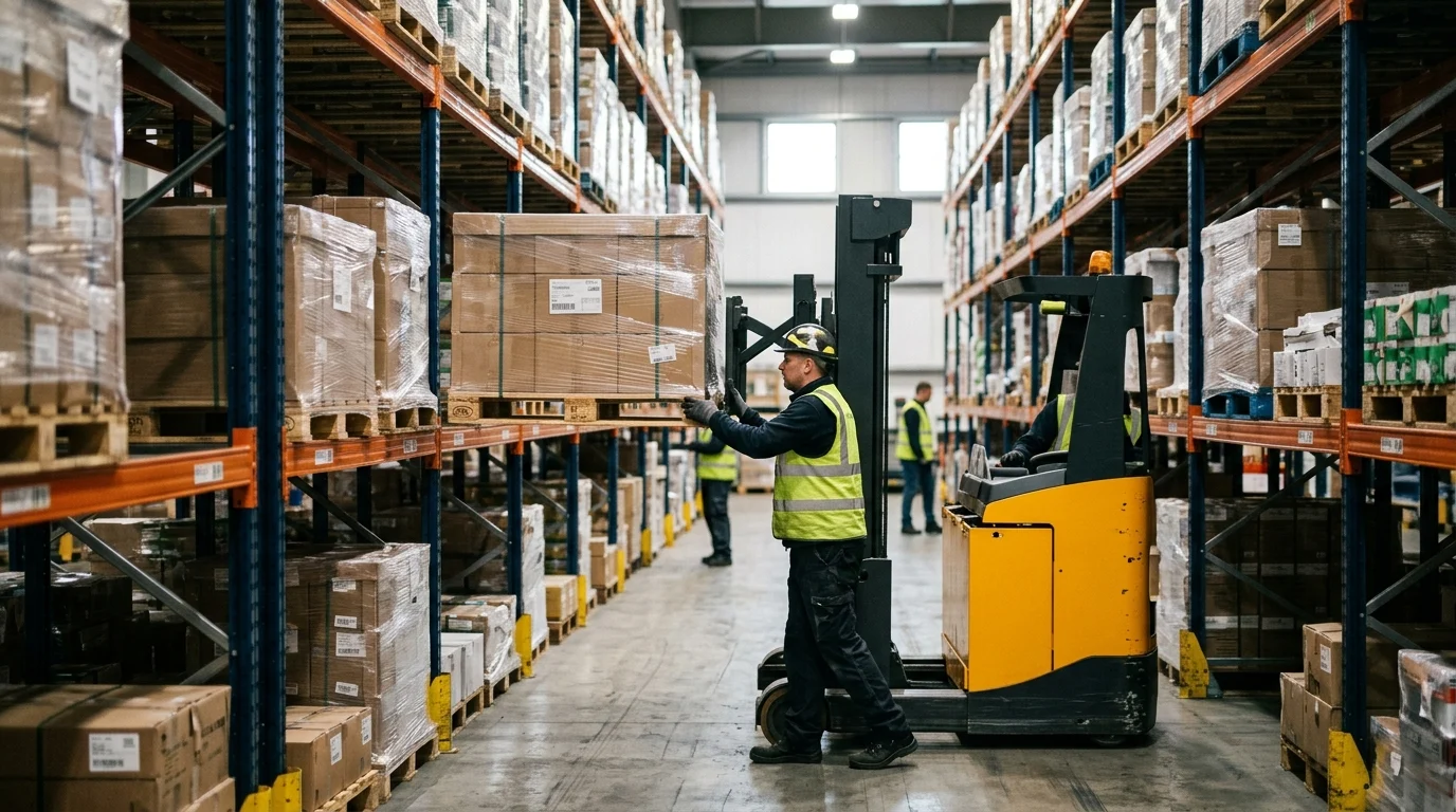
Standardization and supply considerations
The global bearing market is heavily standardized around ISO metric and ABMA inch boundary dimensions. Specifying a standard catalogue bearing from series such as 6200, 6300, or 22200 guarantees multi-source availability, competitive pricing, and immediate replacement availability for end-users. Deviating from these standards introduces significant supply chain friction.
When engineers specify custom internal geometries, proprietary sealing, or non-standard dimensions, they must account for severe logistical penalties. Custom bearings frequently dictate Minimum Order Quantities (MOQs) exceeding 1,000 units and involve manufacturing lead times ranging from 24 to 40 weeks. Unless the application is highly specialized—such as aerospace actuation or ultra-compact robotics—the total cost of ownership heavily favors designing the surrounding housing and shaft to accommodate a standard Commercial Off-The-Shelf (COTS) bearing.
Final decision guidance
The final specification decision should be evaluated through a matrix that weighs technical performance against commercial availability. Engineers should mandate design reviews that challenge the necessity of high-precision tolerance classes (like ABEC 7/ISO P4) or exotic materials if the application does not strictly require them, as these features exponentially increase unit costs.
| Sourcing Strategy | Typical Lead Time | Typical MOQ | TCO Impact | Ideal Application Profile |
|---|---|---|---|---|
| Standard COTS | 1-2 weeks | 1+ | Lowest | General industrial, pumps, standard motors |
| Modified Standard | 8-12 weeks | 100+ | Moderate | Specific clearance (C3/C4), custom grease fill |
| Fully Custom | 24-40 weeks | 1000+ | Highest | Aerospace, high-density robotics, automotive OEM |
Ultimately, successful bearing selection culminates in a comprehensive engineering drawing that explicitly defines not just the part number, but the required clearance, tolerance class, cage material, and lubrication parameters. By rigorously adhering to a mathematically validated and commercially aware selection process, engineers ensure maximum asset availability and safeguard the mechanical reliability of the end product.
Key Takeaways
- The most important conclusions and rationale for Bearing Selection
- Specs, compliance, and risk checks worth validating before you commit
- Practical next steps and caveats readers can apply immediately
Frequently Asked Questions
How do I choose the right bearing type for my machine?
Match the load and speed first: deep groove for general radial loads, angular contact for combined loads, tapered or spherical roller for heavier loads, and needle bearings where space is limited.
When should I use an interference fit instead of a clearance fit?
Use interference fit on the ring under rotating load to prevent creep. Use a clearance or slip fit on the ring under stationary load to simplify mounting and reduce fit-induced stress.
Why is internal clearance important in bearing selection?
Fits and operating temperature can reduce radial internal clearance. Choose the clearance class so the bearing does not preload in service, especially in high-speed, heavy-load, or hot-running machinery.
Which bearing options does DEMY offer for OEM and industrial applications?
DEMY supplies ball and roller bearings including deep groove, angular contact, tapered, cylindrical, spherical, needle, thrust, stainless, ceramic, and self-lubricating types for many machinery uses.
How can I confirm the correct bearing from the DEMY e-catalog?
Check bore, outer diameter, width, load type, speed, fit requirements, and operating environment. Then verify precision class, clearance, and material in the e-catalog or request technical support for final confirmation.
Post time: Apr-23-2026