Why Bearing Failure Matters
Industrial bearings are precision-engineered components designed to facilitate rotational movement while minimizing friction and handling specific load capacities. Under ideal laboratory conditions, a rolling element bearing will operate until it reaches its L10 fatigue life—a statistical metric indicating that 90% of a given bearing population will survive a specified number of revolutions before metal fatigue occurs. For many industrial applications, this L10 life is calculated to exceed 100,000 continuous operating hours.
However, empirical industry data reveals that fewer than 10% of bearings actually reach their engineered fatigue limit. The vast majority succumb to premature failure driven by external operational, environmental, or mechanical variables. Understanding the mechanisms of these failures is critical for plant engineers seeking to optimize asset reliability and maximize operational uptime.
Definition and early warning signs
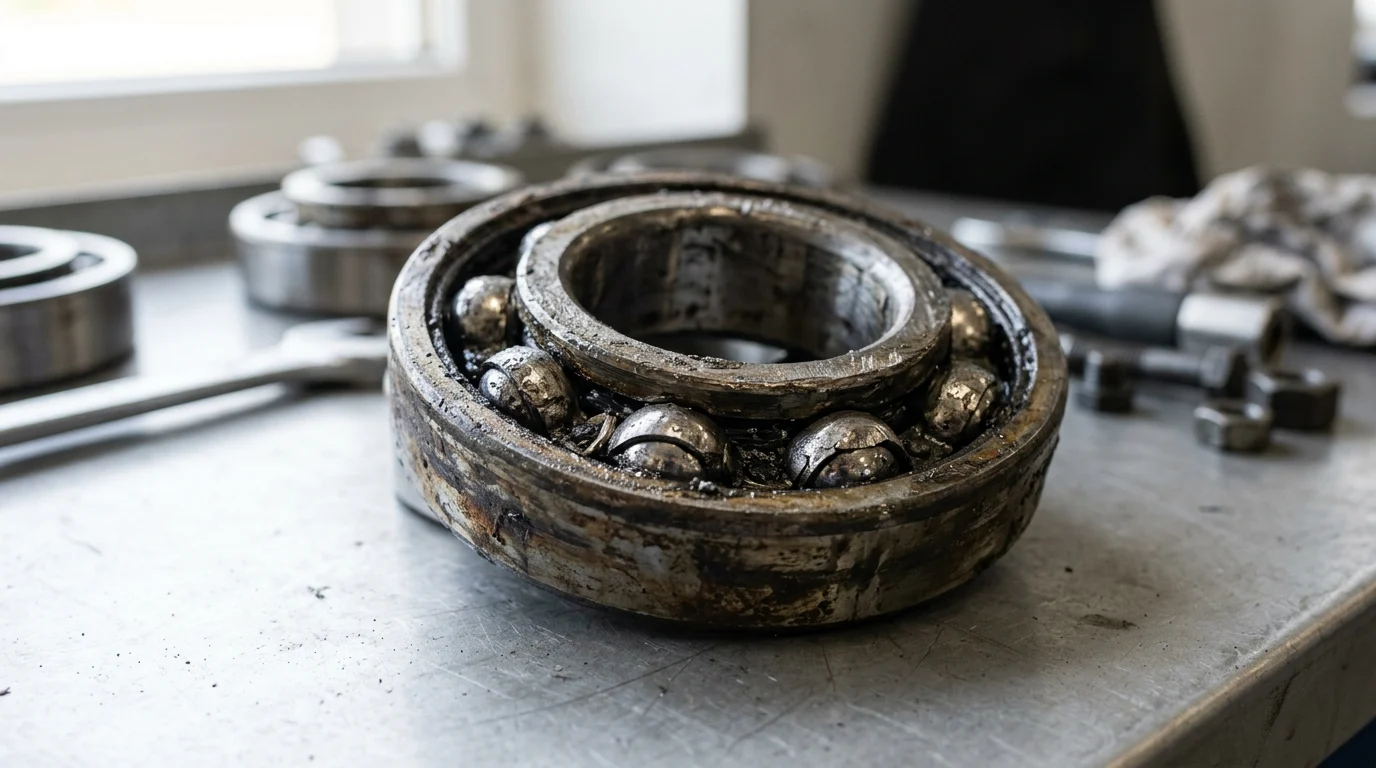
Bearing failure is formally defined as the point at which a bearing can no longer perform its required function within specified performance parameters, typically manifesting as material degradation on the raceways or rolling elements. The progression toward functional failure rarely occurs instantaneously; it follows a predictable degradation curve known as the P-F (Potential to Functional failure) interval. Identifying the earliest anomalies along this curve allows maintenance teams to intervene before catastrophic damage occurs.
Early warning signs are highly quantifiable using condition monitoring technologies. The initial stages of subsurface fatigue generate high-frequency acoustic emissions, often detectable in the 20 kHz to 100 kHz ultrasonic range, long before any physical damage is visible. As subsurface micro-cracks propagate to the surface and cause micro-spalling, the bearing will exhibit increased vibration velocity. For instance, a machine operating smoothly at 1.5 mm/s RMS may slowly trend upward, eventually breaching the ISO 10816 alarm limit of 4.5 mm/s RMS for rigid foundations. Additionally, localized friction increases will cause thermal spikes, often pushing bearing housing temperatures beyond the standard baseline of 60°C to 80°C.
Impact on reliability, safety, and cost
The consequences of unmitigated bearing failure extend far beyond the procurement cost of a replacement component. In continuous process industries, such as petrochemical refining, pulp and paper, or power generation, the primary financial impact is driven by unplanned downtime. A single catastrophic bearing seizure on a critical path asset can halt an entire production line, incurring lost production costs ranging from $10,000 to well over $100,000 per hour, depending on the facility’s output scale.
Furthermore, catastrophic bearing failure introduces severe safety and secondary equipment risks. A seized bearing can cause shaft shearing, coupling destruction, and collateral damage to expensive gearboxes or electric motor stators. In high-speed applications, the intense friction generated during a severe failure can elevate temperatures past the flash point of the lubricant, creating a severe fire hazard.
| Failure Stage | Detection Method | Typical Lead Time to Failure | Financial Impact |
|---|---|---|---|
| Subsurface Fatigue | Ultrasonic / Acoustic Emission | 1 to 6 Months | Minimal (Planned Replacement) |
| Micro-Spalling | High-Frequency Vibration (Enveloping) | 1 to 4 Weeks | Low (Scheduled Downtime) |
| Macro-Spalling | Overall Vibration Velocity / Temperature | Days | Moderate (Urgent Intervention) |
| Catastrophic Seizure | Audible Noise / Smoke / Tripped Breaker | Hours or Minutes | High (Lost Production, Collateral Damage) |
Common Causes of Bearing Failure
While the fundamental limit of a bearing’s lifespan is governed by material fatigue, real-world failure analysis demonstrates that external stressors are the primary culprits. Standardized bearing life equations, such as the ISO 281 standard, rely on the assumption of ideal operating conditions. When these conditions are compromised, the actual operational life drops exponentially.
Industry reliability studies consistently indicate that approximately 80% of all premature bearing failures are directly related to inadequate or improper lubrication. The remaining 20% are largely distributed among contamination, improper mounting techniques, and mechanical overloading. Addressing these root causes requires a deep understanding of the tribological and mechanical thresholds of rolling element bearings.
Lubrication failure and contamination
Lubrication failures occur when the elastohydrodynamic (EHD) oil film, which separates the rolling elements from the raceways, breaks down. This film is astonishingly thin—often between 0.1 and 1.0 micrometers—yet it must withstand contact pressures exceeding 1,000 MPa (145,000 psi). If the lubricant viscosity is too low for the operating temperature, or if grease is under-applied, metal-to-metal contact ensues, leading to adhesive wear and smearing. Conversely, over-greasing cavities beyond 30% to 50% of their free volume causes severe churning, which can rapidly drive operating temperatures above 100°C, accelerating oil oxidation and soap thickener degradation.
Contamination acts as an abrasive compound within the bearing cavity. Solid particle contamination is measured using the ISO 4406 cleanliness code. Operating a hydraulic or circulating oil system at a high contamination level, such as ISO 21/18/15, forces microscopic particulates into the load zone, creating localized stress risers and denting the raceways. Reducing the cleanliness level to a tighter standard, like ISO 16/14/11, can exponentially extend bearing life. Fluid contamination is equally destructive; the presence of just 0.002% (20 ppm) dissolved water in the lubricant can reduce the L10 fatigue life by up to 48% due to hydrogen embrittlement of the bearing steel.
Misalignment, overload, and poor fits
Mechanical deviations from ideal design parameters subject bearings to forces they were not engineered to withstand. Misalignment between the shaft and housing is a frequent driver of edge loading. When angular misalignment exceeds the bearing’s permissible threshold—often as tight as 0.001 radians (1 milliradian) for deep groove ball bearings—the load is forced onto the extreme edges of the rollers and raceways. This localized stress concentration vastly exceeds the material’s yield strength, resulting in rapid flaking and cage fracture.
Overloading, whether static or dynamic, accelerates fatigue failure. According to the foundational bearing life equation (L10 = (C/P)^p, where C is the dynamic load rating, P is the equivalent dynamic bearing load, and p is the exponent for the bearing type), life is inversely proportional to the cube of the load for ball bearings. A mere 20% increase in the applied load (P) reduces the bearing’s expected life by nearly 50%. Poor fits further exacerbate these issues. A shaft fit that is too tight will radially expand the inner ring, eliminating the critical internal clearance and causing thermal runaway. A fit that is too loose will result in the inner ring creeping or spinning on the shaft, causing fretting corrosion and severe dimensional wear.
Installation and handling errors
Human error during the installation phase immediately compromises the structural integrity of a new bearing. The most common handling error is the application of impact forces directly to the bearing rings. Striking a bearing with a steel hammer, or applying mounting force through the rolling elements (e.g., pressing the outer ring to install the bearing onto a shaft), causes true brinelling. This manifests as permanent plastic deformation in the raceways, spaced exactly at the pitch of the rolling elements, permanently ruining the bearing before it ever rotates.
Improper heating techniques also induce irreversible damage. While thermal expansion is a standard method for mounting interference-fit bearings, utilizing an uncontrolled heat source like an oxy-acetylene torch creates extreme localized thermal gradients. Heating standard bearing steel (e.g., AISI 52100) beyond 120°C (248°F) alters its metallurgical microstructure. The retained austenite transforms into martensite, causing dimensional instability and a permanent loss of material hardness, which severely degrades the bearing’s load-carrying capacity.
Lubrication and Contamination Control
Effective lubrication and contamination control form the foundational layer of any proactive bearing reliability strategy. The primary objective is to maintain a specific tribological state: the Lambda ratio. This ratio compares the thickness of the elastohydrodynamic lubricant film to the composite surface roughness of the bearing raceways and rolling elements.
A Lambda ratio of less than 1 indicates boundary lubrication with frequent metal-to-metal contact, while a ratio greater than 2 signifies full fluid film separation, where fatigue life is maximized. Achieving and maintaining this optimal Lambda ratio requires precise lubricant selection, disciplined application intervals, and rigorous exclusion of particulate and moisture ingress.
Selecting the right lubricant and viscosity
Selecting the correct lubricant requires calculating the minimum required kinematic viscosity at the bearing’s specific operating temperature. This is fundamentally driven by the bearing’s pitch diameter (dm) and its rotational speed (RPM). For example, a moderately sized bearing operating at 1,500 RPM might require an ISO VG 68 oil at a standard operating temperature of 60°C. However, if the ambient environment pushes the operating temperature to 90°C, the oil will thin significantly, necessitating a shift to a higher baseline viscosity, such as an ISO VG 220, to maintain the required film thickness.
Beyond base oil viscosity, the selection of the thickener system and additive package is critical. For heavy-load or low-speed applications where the Lambda ratio falls below 1, Anti-Wear (AW) and Extreme Pressure (EP) additives are necessary to form protective sacrificial chemical layers on the steel surfaces. When selecting grease, the National Lubricating Grease Institute (NLGI) consistency grade must match the application; an NLGI 2 grease is standard for most electric motors, while a softer NLGI 1 or 0 may be required for centralized auto-lube systems operating in sub-zero environments to prevent pumpability issues.
Setting relubrication intervals
The transition from subjective, calendar-based greasing to engineered relubrication intervals is a hallmark of advanced reliability programs. Relubrication frequency must account for the bearing type, size, speed, operating temperature, and environmental severity. As a baseline rule, for every 15°C increase in operating temperature above 70°C, the relubrication interval should be cut in half due to the accelerated oxidation rate of the base oil.
Equally important is the precise control of the relubrication volume. A widely accepted industry formula for calculating the correct replenishment amount is V = D × B × 0.005, where V is the grease volume in grams, D is the bearing outside diameter in millimeters, and B is the total bearing width in millimeters. Utilizing ultrasonic grease guns can further refine this process. By monitoring the high-frequency acoustic emissions in real-time while pumping grease, technicians can stop lubricating exactly when the acoustic energy drops to a smooth baseline, indicating optimal film replenishment without over-pressurizing the cavity or blowing out the shaft seals.
Using seals, filtration, and cleanliness targets
Excluding external contaminants is often more cost-effective than attempting to filter them out post-ingress. The selection of bearing housing seals dictates the defense against the environment. Contact seals (such as lip seals) offer excellent protection against fluid ingress but are limited by shaft surface speed limits (typically around 10 to 15 m/s) due to friction and heat generation. For high-speed applications, non-contact labyrinth seals or magnetic bearing isolators are required. These isolators provide IP66-rated protection without physical wear, utilizing centrifugal force and intricate internal pathways to expel contaminants.
In circulating oil systems, stringent filtration targets must be enforced. Utilizing filters with a high Beta ratio (e.g., Beta > 1000 for 5-micron particles, meaning the filter removes 99.9% of particles 5 microns and larger) ensures the fluid remains pristine. Managing the headspace of fluid reservoirs with desiccant breathers is also necessary to prevent ambient moisture from condensing within the oil.
| ISO 4406 Cleanliness Target | Typical Application | Relative Bearing Life Extension (vs. 21/18/15) |
|---|---|---|
| 21/18/15 | Standard industrial, poor filtration | 1.0x (Baseline) |
| 18/16/13 | Upgraded filtration, sealed reservoirs | 1.5x to 2.0x |
| 16/14/11 | Precision hydraulics, high-speed spindles | 2.5x to 3.5x |
| 14/12/9 | Aerospace, extreme precision systems | > 4.0x |
Alignment, Load, and Installation Best Practices
The mechanical precision required to install industrial bearings leaves zero margin for subjective interpretation. Bearings are manufactured to exacting dimensional tolerances, often measured in mere microns (thousandths of a millimeter). Consequently, the shafts and housings that interface with these bearings must be machined and prepared to complementary tolerances.
Deviations in alignment, improper load distribution, or brute-force installation methods will instantly negate the value of high-quality components and premium lubrication. Establishing a standardized, highly controlled installation protocol is mandatory for preventing early-life mortality in rotating equipment.
Managing shaft, housing, preload, and clearance
The relationship between the bearing, the shaft, and the housing is dictated by the principles of fit and internal clearance. Shafts are typically machined to specific ISO tolerance classes (such as j5, k5, or m5) depending on the magnitude of the load and whether the inner ring rotates. An interference fit is generally required for the rotating ring to prevent creeping. However, this interference physically expands the inner ring, consuming a portion of the bearing’s radial internal clearance (RIC).
Engineers must specify the correct initial clearance—such as C2 (tight), Normal, C3 (loose), or C4 (extra loose)—to accommodate this expansion. For example, a standard C3 deep groove ball bearing with a 50 mm bore may have an initial unmounted internal clearance of 15 to 33 micrometers. After an interference fit on the shaft and thermal expansion during steady-state operation, the operational clearance may drop to a near-zero or slight preload condition (e.g., 2 to 5 micrometers). Miscalculating this dynamic expansion and utilizing a Normal clearance bearing in a high-temperature application will result in a negative clearance state, causing catastrophic internal preload, severe friction, and rapid seizure.
Using proper mounting tools and heating methods
The application of force during mounting must be entirely isolated from the rolling elements. For cold mounting small bearings (typically under 50 mm bore), specialized fitting tool kits utilizing impact rings and sleeves ensure that force is applied simultaneously to both the inner and outer rings, preventing brinelling. For larger bearings requiring an interference fit, thermal expansion is the preferred method.
The industry standard for heating bearings is the use of a microprocessor-controlled induction heater. These devices heat the inner ring uniformly while monitoring the temperature to ensure it does not exceed the critical threshold of 110°C (230°F). Crucially, modern induction heaters automatically demagnetize the bearing at the end of the heating cycle to less than 2 A/cm; failure to demagnetize the bearing will cause it to attract ferrous wear particles during operation, accelerating abrasive wear. For exceptionally large spherical roller bearings mounted on tapered shafts, hydraulic nuts and the axial drive-up method are utilized. This technique uses hydraulic pressure to drive the bearing up the taper, reducing the internal clearance by exact micrometer measurements to achieve the perfect interference fit.
Controlling torque and installation damage
Fastening the bearing housing and securing the locking mechanisms require strict adherence to torque specifications. Uneven tightening of housing split-lines or end-covers can distort the outer ring of the bearing, creating a pinch point that pinches the rolling elements as they pass through the load zone. Technicians must use calibrated torque wrenches and follow a star-pattern tightening sequence to ensure uniform clamping force.
Installation damage also includes static overload events while the machine is offline. Transporting heavy machinery via rail or truck without properly blocking the rotor can subject the stationary bearings to severe vibrational impacts. This phenomenon, known as false brinelling, causes microscopic fretting wear marks at the exact spacing of the rolling elements due to the absence of a protective hydrodynamic oil film during static vibration. To prevent this, rotors weighing several tons must be securely blocked, or the bearings must be placed under a heavy axial preload during transit to prevent micro-movements.
Bearing Failure Prevention Program
Transitioning a facility from a reactive run-to-failure posture to a predictive maintenance (PdM) strategy is the ultimate defense against bearing-related downtime. A formalized bearing failure prevention program integrates condition monitoring technologies, rigorous failure analysis, and data-driven lifecycle management.
The return on investment for such programs is substantial. Industrial reliability data demonstrates that implementing a comprehensive PdM program can reduce overall maintenance costs by 25% to 30%, eliminate up to 75% of unexpected breakdowns, and extend the mean time between failures (MTBF) of critical rotating assets by years.
Tracking vibration and temperature trends
Continuous or route-based condition monitoring is the primary diagnostic tool in a prevention program. Vibration analysis, specifically high-frequency enveloping or demodulation, allows analysts to isolate the specific defect frequencies of a bearing. Every bearing possesses unique fault frequencies based on its geometry: Ball Pass Frequency Outer (BPFO), Ball Pass Frequency Inner (BPFI), Ball Spin Frequency (BSF), and Fundamental Train Frequency (FTF). Detecting a peak at the BPFO, for instance, confirms a defect on the outer raceway.
Establishing precise alarm thresholds is critical for actionable data. A common industry practice sets an Alert alarm at a 2x increase over the baseline vibration amplitude, prompting closer monitoring and lubrication checks. A Fault or Action alarm is triggered at a 3x to 4x increase (e.g., jumping from 2.0 mm/s to 8.0 mm/s RMS), signaling the need to schedule an immediate replacement. Thermography complements vibration data; routine infrared scans of bearing housings can quickly identify assets operating outside their engineered thermal envelopes, flagging potential over-lubrication, under-lubrication, or misalignment issues before mechanical degradation occurs.
Inspecting wear patterns and root causes
When a bearing is ultimately removed from service, it should not be summarily discarded. Conducting a root cause failure analysis (RCFA) on the damaged component is essential for preventing recurring failures. The ISO 15243 standard provides a comprehensive classification system for bearing damage and wear patterns, dividing failures into categories such as fatigue, wear, corrosion, electrical erosion, plastic deformation, and cracking.
Inspecting the load zone path inside the bearing yields critical clues about the machine’s operating conditions. A normal load path on a radially loaded deep groove ball bearing extends slightly less than 180 degrees around the stationary outer ring. If the inspection reveals a load path that is heavily skewed to one side, it indicates severe angular misalignment. If the load path encompasses the entire 360 degrees of the outer ring, the bearing was operating under a severe internal preload or a tight housing fit. Microscopic inspection can differentiate between abrasive wear (dull, frosted surfaces caused by particle contamination) and adhesive wear (smearing and metal transfer caused by inadequate lubrication film thickness).
Key Takeaways
- Monitor vibration, temperature, ultrasound, and lubricant condition to detect bearing defects during the P-F interval before functional failure occurs.
- Use the correct lubricant type, quantity, and relubrication schedule because lubrication problems are one of the fastest paths to premature bearing damage.
- Prevent contamination with proper seals, clean handling, and controlled storage because dirt, moisture, and debris can damage raceways and rolling elements.
- Follow correct mounting procedures and alignment practices to avoid brinelling, uneven load distribution, shaft stress, and early fatigue.
- Select bearings based on actual load, speed, environment, and precision requirements rather than size alone to improve service life and reliability.
- Treat rising housing temperatures above normal baselines and vibration trends approaching alarm limits as maintenance triggers, not minor operating variations.
Frequently Asked Questions
What are the most common causes of bearing failure?
The most common causes include poor lubrication, contamination, improper installation, misalignment, excessive load, and unsuitable bearing selection for the application.
How can I tell if a bearing is starting to fail?
Early warning signs include rising vibration, abnormal noise, heat buildup, lubricant discoloration, reduced machine efficiency, and ultrasonic emissions before visible damage appears.
Why do many bearings fail before reaching their rated life?
Although many bearings are engineered for long L10 fatigue life, premature failure often results from operating conditions such as contamination, overloading, poor lubrication, or mounting errors.
How often should bearings be lubricated?
Lubrication intervals depend on bearing type, speed, load, temperature, and environment. Follow manufacturer guidance and adjust based on condition monitoring, lubricant analysis, and operating severity.
Can the right bearing selection reduce failure risk?
Yes. Selecting the correct bearing type, load rating, material, clearance, and sealing design helps match the bearing to real operating conditions and prevents avoidable premature damage.

Demy
holder bearings and roller chain accessories. Proprietary hightemp rubber seal technology outperforms standard NBR seals,providing tight sealing and extended product lifespan.
Equipped with semi-automatic and fully automatic production lines for high-quality, efficient manufacturing with fast delivery for urgent orders.
Post time: Jun-16-2026